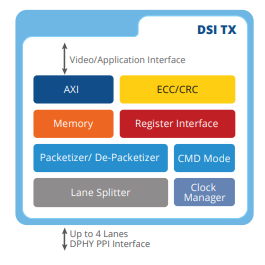
Description and Features
MIPI is the Mobile Industry Processor Interface that provides specification for software and hardware interfaces in mobile terminals and thereby encouraging the adoption of these standards throughout the industry chain for achieving interoperability has come up with many specifications like CSI, DSI, DPHY, CPHY, MPHY, SoundWire, UniPro and more. This document details the design implementation of MIPI Sound wire. DSI specifies the interface between a host processor and a peripheral such as a display module. It builds on existing MIPI Alliance specifications by adopting pixel formats and command set specified in DPI-2, DBI- 2 and DCS standards. From a conceptual viewpoint, a DSI-compliant interface performs the same functions as interfaces based on DBI-2 and DPI-2 standards or similar parallel display interfaces. It sends pixels or commands to the peripheral, and can read back status or pixel information from the peripheral. The main difference is that DSI serializes all pixel data, commands, and events that, in traditional or legacy interfaces, are normally conveyed to and from the peripheral on a parallel data bus with additional control signals. Below is a simple system representation of DSI.
Features
-
Programmable 1, 2 or 4 Data Lane Configuration.
-
Compliant to mipi_DSI_specification_v1-2.pdf
-
Forward and reverse LP communication (1 lane).
-
Supports ECC and CRC generation.
-
1-bit ECC error detection and correction in reverse LP mode communication.
-
2-bit ECC detection and Error reporting in reverse LP mode communication.
-
CRC checking and error reporting in reverse communication.
-
Supports all type of short and long packets
-
Supports LP mode reverse communication.
-
D-PHY error reporting.
-
DSI Error checking and reporting.
-
Supports reset trigger message.
-
Configurable Virtual Channel. Upto 4 Virtual channel.
-
Pixel Interface: 16, 18 and 24 and 36 bits per pixel
-
Operate in continuous and non-continuous clock modes.
-
Command and Video Mode (Burst and Non-Burst mode) support
-
In command mode, Data Lane supports: CIL-MFAA (HS-TX, LP-TX, LP-RX, LP-CD)
-
In command mode, Clock Lane supports: CIL-MCNN (HS-TX, LP-TX)
-
In Video mode, Data Lane supports: CIL-MFAN (HS-TX, LP-TX)
-
In Video mode, Clock Lane supports: CIL-MCNN (HS-TX, LP-TX)
-
Switching to LP mode or staying in HS mode by transmitting blanking packets supported.
-
EOTP can be enabled or disabled.
-
Backward compatibility with earlier version of DSI devices.
-
Option to check for CRC/ECC in reverse communication packets to be compatible with peripheral.
-
Non-burst mode with Sync Pulse, Non-burst mode with Sync event, Burst modes are supported.
-
Supports Stereoscopic image data.
-
Supports Compression encoder complaint to VESA Display Stream Compression Standard V1.1
Deliverables
-
Configurable RTL Code
-
HDL-based test bench and behavioral models
-
Test cases
-
Protocol checkers, bus watchers, and performance monitors
-
Configurable synthesis shell
-
Documentation
-
Design guide
-
Verification guide
-
Synthesis guide
Benefits
-
Highly modular and configurable design
-
Layered architecture
-
Active low async reset
-
Clearly de-marked clock domains
-
Extensive clock gating support
Applications
-
Consumer
-
Automotive
-
Enterprise
