SCR intro:
Silicon-controlled rectifiers (SCRs) are interesting devices that can be used for on-chip ESD protection, if (and only if) they are properly designed and biased. SCRs are used for high-speed/RF or low-capacitance, small area/high-performance ESD solutions in all CMOS technologies, including SOI and FinFET (down to 3nm today).
SCR operation:
Figure 1 introduces the SCR equivalent schematic (a), a typical cross-section found in CMOS circuits (b) and an example thereof – a CMOS invertor (c). To understand its operation, we need to look at both (a) and (b). We see an PNP connected to a NPN device, together forming an NPNP structure; this 4-layer structure forms an SCR.

(a)

(b)

(c)
Figure 1: The schematic of an SCR (a), the cross-sectional view of an invertor with inherent SCR (b), and the schematic of an invertor (c).
For better understanding, Figure 2.a combines a cross-section and a schematic.

(a)

(b)
(c)
Figure 2: The cross-section of an invertor with an SCR(a), the equivalent schematic of an SCR to help to understand (a), and the current path through the SCR for anode-cathode bias (c).
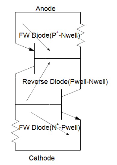
From the anode i.e., the P+ source of the PMOS versus the cathode i.e., the N+ source of NMOS, we see (for a positive anode to cathode bias) in series: a forward diode, a reverse diode, and a forward diode, as illustrated in Figure 2.c. The reverse diode is the Nwell-Pwell diode which doubles as the collector-base junction for both the PNP and the NPN.
Until the well junction breaks down, no current is flowing through the SCR structure. Obviously, this changes when the latter breakdown occurs. For a basic SCR, this will happen at a high voltage (equal to the well-well breakdown plus 2 forward diode drops). We expect to see a reverse breakdown current-voltage characteristic as depicted in Figure 3.

Figure 3: expected I-V curve of an SCR.
However, this is not the case, at least when the beta product of the PNP and the NPN is higher than 1. Have a look at Figure 4 and follow this narrative, to understand how bipolar operation collapses the voltage across the SCR and sinks a large current…

Figure 4: How the avalanche between two wells collapses the voltage across the SCR.
The avalanche source draws current through the well resistors (both N and P), providing bias to the bases of the bipolars (both PNP and NPN). When that bias exceeds a forward voltage drop, E-B current will flow in the PNP as well as in the NPN. These base currents will be multiplied by the respective betas of the bipolars to deliver C-E current in both the PNP and NPN.
A runaway situation occurs when the beta product is larger than 1, because the E-C current of the PNP increases the base bias of the NPN, and the same is true for the C-E current of the NPN: it increases the base current of the PNP. It is straightforward to see that as base currents are multiplied, the collector currents increase these base currents again, pushing higher collector currents again: we have a positive feedback mechanism as long as there is sufficient voltage bias to keep the bipolar transistors on: the SCR is fully turned on, and can sink a very large current.
Typical SCR ESD current capability, across CMOS generations, is shown in Figure 5. Take this data as a reference, not as absolute values, as devices and performances may vary across processes and foundries.

Figure 5: current capability of an SCR for different technology nodes.
Sofics is highly specialized in the design and use of SCR devices. For more info about Sofics’ experience please have a look at the following links:
FinFET : https://monthly-pulse.com/category/process-type/finfet/
SOI : https://monthly-pulse.com/category/process-type/soi/
Low leakage solutions: https://monthly-pulse.com/category/requirements/low-leakage/
Sofics IP portfolio : https://monthly-pulse.com/category/sofics-ip-portfolio/takecharge/[KV1]

One thought on “ESD basic: Silicon Control Rectifier (SCR)”
Comments are closed.