
In my most recent blog post, I reminisced about childhood toys that let you construct complex structures from simple elements (blocks, bricks, girders, etc.) Many of us still enjoy these toys as adults. I’ve heard many parents say that one of their favorite activities with their youngsters is sitting down in front of a tub of LEGO parts and working together on some elaborate construction. I noted that assembling all the pieces of a complete system on chip (SoC) is not nearly as much fun, and discussed how IDS-Integrate™ in our IDesignSpec™ (IDS) Suite can help. Today I’m going to fill in some details.
A Quick IDS-Integrate Summary
When we introduced this product several years ago, our goal was to reduce or even eliminate the manual assembly of complex chips. Making hundreds of thousands of inter-block connections by hand is tedious and error-prone. It wastes precious human resources that could be better engaged in innovative design. Debugging the inevitable typos and other errors in manual interconnection takes even more resources, and delays your tapeout schedule as well.
I noted that simple spreadsheet-driven scripts help a bit, but they’re insufficient for large designs. A complete chip assembly solution must:
- Work at every level of hierarchy, all way up to the complete SoC
- Interconnect signals that pass up and down through levels of hierarchy
- Generate bus “widgets” such as bridges, converters, aggregators, and crossbars
- Rerun quickly and automatically as your design evolves throughout the project
- Modify the hierarchy to reflect any changes made by place-and-route (P&R) tools
IDS-Integrate has all these capabilities and more. We read in Library Exchange Format (LEF) and Design Exchange Format (DEF) files and ensure that the assembled chip is consistent with the post-layout results. We read in Unified Power Format (UPF) files and ensure that hierarchical power structures are preserved. We read in synthesis design constraint (SDC) files to help ensure timing closure. Finally, we generate SoC-level UPF and SDC files along with the RTL interconnect design and any relevant bus widgets and interfaces from our Silicon IP Portfolio.
A Few Concrete Examples
Since different users have different preferences, we make our API available in both Python and Tcl formats. For example, if you want to read in an RTL file with a GPIO design, you might use the following Python command:
soc_read("+incdir+idsng_gpio/inc", search_path="idsng_gpio", file="gpio_top.v")
The same command in Tcl looks like this:
soc_read +incdir+idsng_gpio/inc -search_path "idsng_gpio" -file gpio_top.v
To be fair to all readers, I’ll provide some of the remaining examples in Python and some in Tcl. The mapping between the two formats is clear. If you want to create a new block, such as the top level for your SoC, you can specify:
soc_create("top",type="block", name="wrapper_top", bus="ahb", param="param_dict")
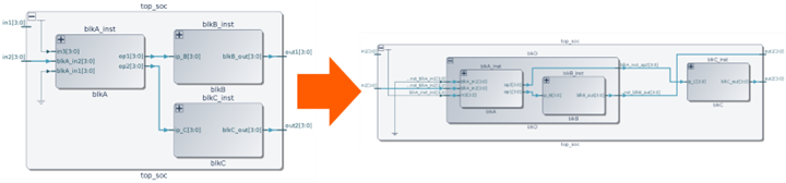
You can easily move blocks around to rearrange the hierarchy as you wish. For example, the following command creates a new block in the top level of the SoC and moves into it two blocks that were formerly at the top level.
soc_move("create", source=["blkA_inst", "blkB_inst"], dest="blkD")
Clearly, typing one line is much faster than hand-editing the RTL files to make all these changes. Specifying connections is also easy, and very flexible. The following examples show connecting matching ports on two blocks, connecting with a bus, and connecting portions of multi-bit ports.
soc_connect -source block1_inst -dest Block2_inst
soc_connect -source block1_inst -dest HFC_INST -bus ahb
soc_connect -source block1_inst.p5[0:7] -dest block2_inst.b1[1:8]
One reason that our API approach is more flexible and less labor-intensive than a full spreadsheet with every signal listed is that we allow wildcards. The following example connects all ports, except for the specified exclusions:
soc_connect_auto(port="*", bus="a.*", exclude={"bus":["blk_1_inst.apb"],"port":"blk_2_inst.a"})
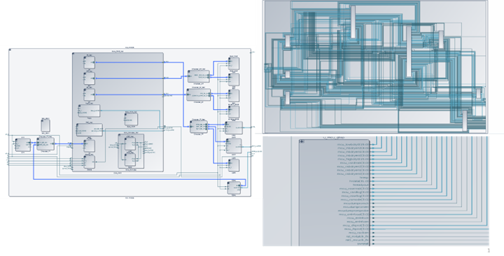
We offer many ways to review the results, including design checks and visualizations such as hierarchy graphs and schematic diagrams:
Once you’re happy with the results, you can write out the RTL design in Verilog and SystemVerilog formats, along with an IP-XACT description:
soc_generate(out=["v","sv","IP-XACT"],dir="RTL_O",header_line_comment, no_include)
Conclusion
In the length of a blog post, I’ve only been able to touch on a few examples of how IDS-Integrate can save you a huge amount of project resources and schedule time. We have a lot more information available, from demos and webinars to documentation and training. Please contact us if you’d like to learn more.