By J. Greg Nash, Centar LLC, Los Angeles, California
(www.centar.net)
Introduction
There is a natural preference to use floating-point implementations in custom embedded applications because they offer a much higher dynamic range and as a byproduct bypass the design hassle of analyzing fixed-point word-lengths, including how to properly “scale” operations to minimize word growth and avoid overflow. Additionally, many applications such as professional audio, industrial measurement/process control, imaging radar, signal intelligence and scientific computing inherently require a high dynamic range so that floating-point support is a necessity. Unfortunately, the arithmetic complexity of using floating-point poses implementation issues and consequently fixed-point FFT implementations have historically been more common in embedded applications.
Here we discuss Centar’s floating-point FFT technology which provides IEEE754 single-precision outputs, yet is much more hardware efficient. For example in the FPGA domain, which is the focus of this note, comparisons show that other designs use up to 100% more logic elements. Such reduced hardware can move the tradeoffs between fixed and floating-point attractively in the direction of the floating-point option. Centar’s design also has better numerical properties.
Fixed vs Floating-point
During the course of an FFT computation it is well known that to avoid loss of dynamic range, numerical issues much be dealt with at each butterfly computation stage, leading to a variety of tradeoffs. For example, to minimize hardware resources, the word length could be kept the same by rounding results after appropriate groups of operations, but in this case dynamic range would suffer. Alternatively, word lengths could grow a fixed number of bits after each butterfly operation to accommodate worst case numerical properties; however, for normal inputs, the extra hardware often isn’t required.
Another common approach, although it is usually adds more circuit hardware, is to use a “block” floating-point number representation. In this case the intermediate results are scaled together only if there is overflow is detected in some part of the circuit. At the end of the computation the total scaling is represented by a single exponent that is associated with each output FFT block of data. This is often a good compromise between the first two strategies.
Centar Fixed-point FFT
The approach Centar uses for its fixed-point circuits is a very sophisticated block-like floating-point approach. Centar’s programmable circuits start with a user chosen matrix representation of the discreet Fourier transform (DFT), as for example representation of a 256-pt transform by a 16x16 matrix. The circuit is designed so that each row of this DFT matrix, as computations are being performed, has its own block floating-point exponent, so that there are 16 exponent values for this 256-point FFT.
During the last stage of the computation, full floating-point is used, so that the “fixed-point” design actually produces an output data set with potentially a different exponent for each data element. At the end of the FFT computation, the 16 block exponents are added to those generated during the last stage of the computation. So in actuality Centar’s fixed-point designs are a hybrid between block-floating-point and true floating-point.
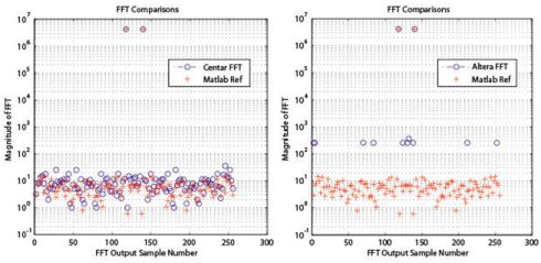
A “fixed-point” FFT output for a single, full scale, 16-bit real sinusoid input is shown in the Fig. 1 below for a 256-point transform. Here a visual comparison with a 16-bit Altera FFT having the same functionality and using a traditional block floating-point approach shows typically ~24db less dynamic range. So the basic scaling approach Centar uses does a good job in maximizing dynamic range for a given fixed-point implementations.

Fig. 1. Comparison Centar (left) and Altera (right) 16-bit fixed-point streaming FFT output magnitudes for a full scale real sinusoidal input
(Note that Centar’s circuit outputs can be a traditional fixed-point result with a single word representing each output, a traditional block-floating-point output with one exponent per block or an output with separate exponents for each data element. Output conversion circuits are used to supply customers their desired formats.)
Centar Floating-point FFT
Because Centar uses a scaling methodology that is already partly based on floating-point, extending it to full single-precision floating-point is relatively straightforward. For example the fixed-point hardware already contains register hardware for both the block exponents mentioned above and a separate exponent for each point, so little additional overhead there is needed.
The main reason for the increased hardware of a single-precision circuit is that it must support a large mantissa (24-bits) and a larger exponent (8-bits) for IEEE 754. Little additional control hardware is necessary over the fixed-point approach.
The main hardware issue that results is that the clock frequencies are significantly reduced compared to smaller fixed-point designs because of the large multipliers needed to support 24-bit twiddle operations. With Altera FPGA DSP blocks, there is no way to add additional internal pipeline stages to increase the DSP block frequencies. For 40nm (Stratix IV/Virtex 6) FPGAs the maximum clock frequencies (and sample rates) are ~350 MHz, whereas for a 16-bit fixed-point design, Centar’s sample rates are greater than 500MHz in 65nm technology (Stratix III/Virtex 5).
Comparisons
Here performance and resource usage data is provided on 256/1024-point, streaming FFTs. The circuits were compiled using Altera’s software tools (Quartus II v15) using a Stratix IV EP4SE230F29C2 FPGA (40nm technology). The TimeQuest static timing analyzer was used to determine maximum clock frequencies (Fmax) at 1.1V and 85C (worst case settings). The same Quartus settings were used for both the Centar and Altera designs (IP v15).
Some minor differences in the circuits were that the Altera design only does forward transforms; whereas the Centar design is bi-directional. (Altera IP v15 for reverse and bi-directional configurations do not produce natural order outputs.) Also, the Centar design below is based on 24-bit fixed-point inputs, whereas the Altera design accepts an IEEE754 format. (Floating point inputs are an option.)
In Table 1 below the adaptive logic module (ALM) is the basic unit of a Stratix IV FPGA (one 8-input LUT, two registers plus other logic) 1. The “v2” Centar design replaces some M9K memories with LUTs in the FPGA fabric.
Table 1. Comparison of single-precision floating-point circuits (IEEE754 outputs) using Stratix IV FPGAs.

From the table it can be see that for the important LUT/register fabric the Altera designs use many more resources, e.g., as many as 100% more ALUTs for the 1024-point transform. This also implies much more power dissipation, as our experience shows this is where most of that dissipation occurs. Also, Altera memory usage is more too, 90/45% for 256/1024-point designs. The Centar designs use significantly more embedded multipliers, but most of the FPGA designs we’ve seen aren’t multiplier limited.
Precision and Dynamic Range
In the Table 2 below are accuracy measurements for 256/1024-pt streaming floating-point single-precision FFTs calculated based on 100 blocks of random 24-bit real and imaginary input data (random phase) obtained from Matlab simulations (Altera’s model is generated by IP v15). The comparison reference is a double precision Matlab calculation.
The “mean absolute error” numbers are obtained by subtracting the reference output from each circuit output, taking the magnitude of this and then dividing by the magnitude of the reference value for that output point. The “maximum absolute error” is the largest of these errors computed over all 100 blocks of input data.
Table 2. Error comparisons for single-precision floating-point FFTs

In terms of mean absolute error and standard deviation the Altera designs here are ~x2 less accurate. It is also noteworthy that maximum errors found for the Altera designs can be ~x10 worse.
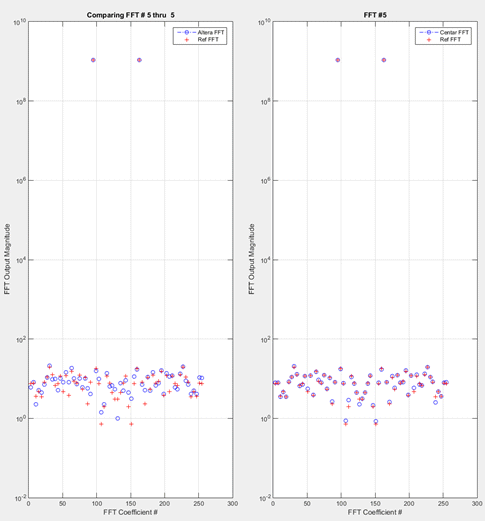
To see these results visually, an example 256- point output is shown Fig. 2 below, compared to outputs from Matlab reference calculation (double precision). To get good results with such an input type requires both high dynamic range and high precision, a very important consideration for applications where small signals need to be seen in the presence of very large signals. (In terms of the signal-to-noise-quantization-ratio both Centar designs in Table 2 have values >150db.)

Fig. 2. Comparison of FFT output magnitudes for 256-pt Centar (right) and Altera circuits (left). (Here the input is a single, full-scale real sinusoid.)
Conclusion
The choice of floating-point vs fixed-point implementations is often a difficult one, which isn’t surprising considering the number of tools available to help evaluate such tradeoffs, i.e., the Matlab fixed-point toolbox; however, the floating-point option doesn’t have to use an unreasonable amount of hardware, as can be seen in the comparison in Table 1 above. And when coupled with significantly reduced design effort and design time, this can easily tip the scales in the direction of a floating-point implementation.
1 Comparison with Xilinx Virtex 6 devices (also 40nm) can be made by noting that two M9K memories are equivalent to a Xilinx BRAM and that an ALM is equivalent to between 1.2 and 1.8 LEs. These numbers come from benchmark studies which show 1 ALM=1.2 LEs (Xilinx white paper WP284 v1.0, December 19, 2007) and 1 ALM=1.8 LEs (Altera white paper), respectively. These papers actually compare Stratix III and Virtex 5 FPGAs; however, the Stratix IV/Virtex 6 architectures are similar so the comparisons should still be good.
